Maytag MERIT PLUS SERIES MPE-33R User Manual
Browse online or download User Manual for Kiln Maytag MERIT PLUS SERIES MPE-33R. Maytag MERIT PLUS SERIES MPE-33R User Manual
- Page / 20
- Table of contents
- TROUBLESHOOTING
- BOOKMARKS
- MERIT PLUS SERIES 1
- IMPORTANT 2
- CAUTION 2
- FRAMING SPECIFICATIONS 4
- FIREPLACE SPECIFICATIONS 4
- MANUAL CONTROL PANEL 6
- CAUTIONS 7
- WARNING 10
- POTENTIOMETER 12
- Installing Wall Thermostat 13
- (optional kit, see Page 18) 13
- TROUBLESHOOTING 15
- REPLACEMENT PARTS 16
- Front View 17
- Face Panel 18
- Mission Style 18
- Interlocking Arch 18
- 1110 West Taft Avenue 20
- Orange, CA 92865 20
Summary of Contents
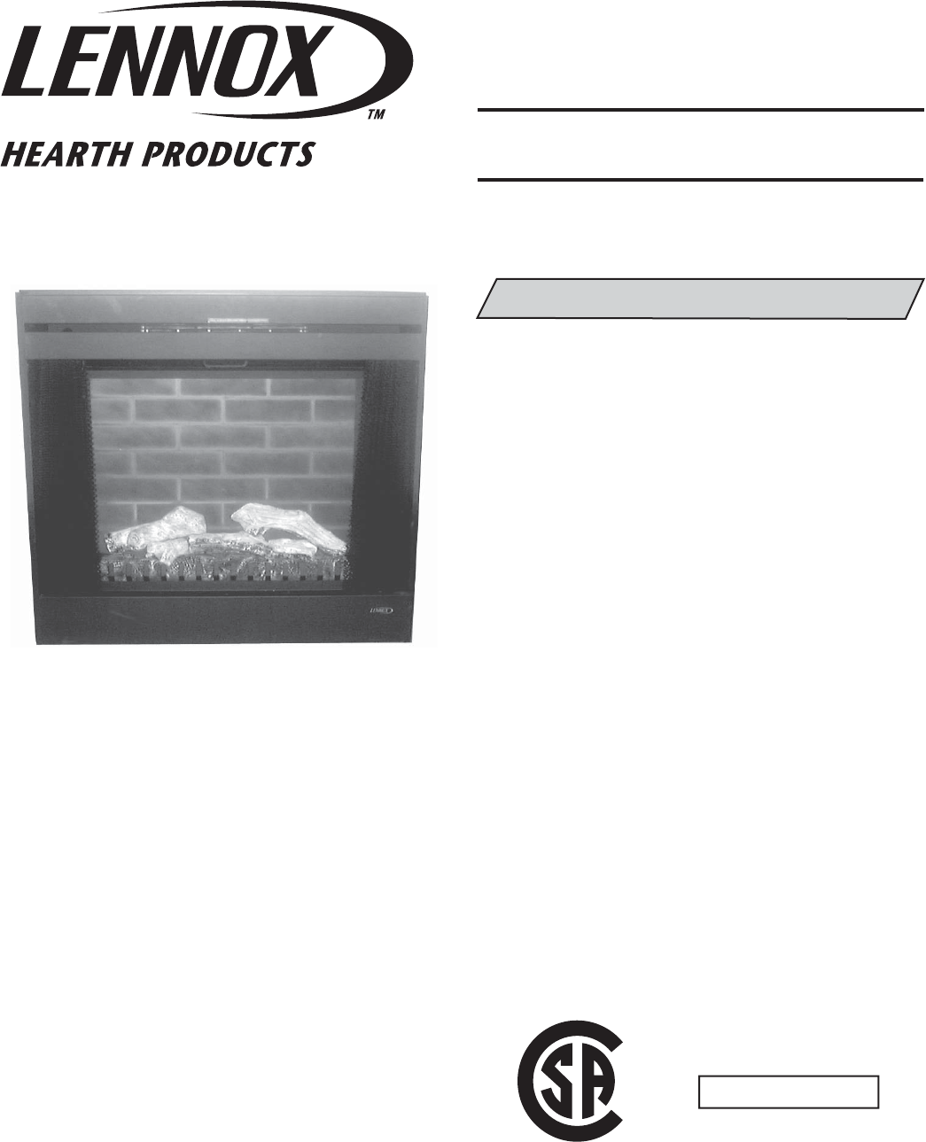
33" Electric FireplaceP/N 850,032M REV. B 06/2006MODEL:SAVE THESE INSTRUCTIONSFOR FUTURE REFERENCEMERIT PLUS SERIESThis manual will enable y
NOTE: DIAGRAMS & ILLUSTRATIONS NOT TO SCALE.1010WIRING DIAGRAM - 120 VOLTWiring diagrams are provided here for reference purposes only. This info
NOTE: DIAGRAMS & ILLUSTRATIONS NOT TO SCALE.11WIRING DIAGRAM - 240 VOLTWiring diagrams are provided here for reference purposes only. This inform
NOTE: DIAGRAMS & ILLUSTRATIONS NOT TO SCALE.125 VGROUNDINSIDEPOWER ON/OFF SWITCH (ON CONTROL PANEL)POWER ON/OFF SWITCH (OPTIONAL WALL SWITCH)OUTSI
NOTE: DIAGRAMS & ILLUSTRATIONS NOT TO SCALE.13Wall ThermostatBlack5 VLeft Side of FireplaceInstalling Wall Thermostat(optional kit, see Page 18)Wi
NOTE: DIAGRAMS & ILLUSTRATIONS NOT TO SCALE.14Power On/Off Wall Switch Installation(optional kit, see Page 18)Wire the wall switch prior to instal
NOTE: DIAGRAMS & ILLUSTRATIONS NOT TO SCALE.15TROUBLESHOOTINGSYMPTOMPOSSIBLECAUSESWHO PERFORMS CORRECTIVE ACTION CORRECTIVE ACTION 1. Fireplace tu
NOTE: DIAGRAMS & ILLUSTRATIONS NOT TO SCALE.16REPLACEMENT PARTSITEMNO.DESCRIPTION MPE-33RCAT. NO. QTY1Bulb Kit, (10 Each 35w Halogen)H1623 12Side
NOTE: DIAGRAMS & ILLUSTRATIONS NOT TO SCALE.17REPLACEMENT PARTS COMPONENT DIAGRAMS - MPE-33R8b14161114256671213152317198a32019Front View18POWERON/
NOTE: DIAGRAMS & ILLUSTRATIONS NOT TO SCALE.18ACCESSORY COMPONENTSThe following items are available for use with this appliance.Cat. No. Model D
NOTE: DIAGRAMS & ILLUSTRATIONS NOT TO SCALE.19NOTE: THIS PAGE LEFT BLANK INTENTIONALLY
NOTE: DIAGRAMS & ILLUSTRATIONS NOT TO SCALE.2INTRODUCTIONThis Electric Fireplace is designed for residential applications to be framed in as a fi r
NOTE: DIAGRAMS & ILLUSTRATIONS NOT TO SCALE.Printed in U.S.A. © LENNOX HEARTH PRODUCTS 2005P/N 850,032M REV. B 06/2006The manufacturer reserves
NOTE: DIAGRAMS & ILLUSTRATIONS NOT TO SCALE.3Figure 1TOOLS AND BUILDING SUPPLIESNORMALLY REQUIREDTools: Phillips Screwdriver 7/16" Socket Dr
NOTE: DIAGRAMS & ILLUSTRATIONS NOT TO SCALE.4FRAMING SPECIFICATIONS34-1/2"(876 mm)21-1/8 "(537 mm)14-7/8"(32 mm)5-1/8 "(130 mm
NOTE: DIAGRAMS & ILLUSTRATIONS NOT TO SCALE.5MINIMUM CLEARANCES TO COMBUS-TIBLESMantel Clearance: Combustible and Non-com-bustible mantels may be
NOTE: DIAGRAMS & ILLUSTRATIONS NOT TO SCALE.6MANUAL CONTROL PANELMain Power On/Off (rear most switch)Figure 4FINAL FINISHINGMaterials such as bric
NOTE: DIAGRAMS & ILLUSTRATIONS NOT TO SCALE.7• When using the remote control, the power on/off switch inside the body and the wall switch (option
NOTE: DIAGRAMS & ILLUSTRATIONS NOT TO SCALE.8Figure 9MAINTENANCEThis appliance has been designed to provide many years of trouble-free service. Th
NOTE: DIAGRAMS & ILLUSTRATIONS NOT TO SCALE.9Replacing Light Bulbs b. Flame Cylinder Bulbs i. Remove Brick panel, following proce-dure on Page 8
Related products and manuals for Kiln Maytag MERIT PLUS SERIES MPE-33R


 (9 pages)
(32 pages)
(12 pages)
(56 pages)
(14 pages)
(24 pages)
(68 pages)
(68 pages)
(8 pages)
(27 pages)
(20 pages)
(40 pages)
(20 pages)
(9 pages)
(0 pages)
(14 pages)
(32 pages)
(56 pages)
(9 pages)
(32 pages)
(12 pages)
(56 pages)
(14 pages)
(24 pages)
(68 pages)
(68 pages)
(8 pages)
(27 pages)
(20 pages)
(40 pages)
(20 pages)
(9 pages)
(0 pages)
(14 pages)
(32 pages)
(56 pages)
© 2020, manymanuals.com. All rights reserved. | 3.589 s |
 Manymanuals.com
 Manymanuals.de
 Manymanuals.fr
 Manymanuals.it
 Manymanuals.pl
 Manymanuals.cz
 Manymanuals.es
 Manymanuals-pt.com
Comments to this Manuals